
Introduction
A bootloader is a critical piece of software responsible for initializing the hardware and loading the main application. Whether you’re working on a custom project or exploring how embedded systems boot up, understanding bootloaders is essential. In this blog post, I’ll guide you through writing a simple bootloader from scratch for the STM32F4 microcontroller, a popular choice among developers.
You’ll learn the basics of what a bootloader does, how to set up your development environment, and how to write and test your first bootloader. You can find the complete code on my GitHub repo.
Understanding Bootloaders
A bootloader is the first code that runs when a microcontroller is powered on or reset. Its primary responsibilities are:
- Initializing the hardware (e.g., setting up the clock, configuring GPIOs).
- Loading the main application from a specific memory location.
- Jumping to the main application’s entry point to start execution.
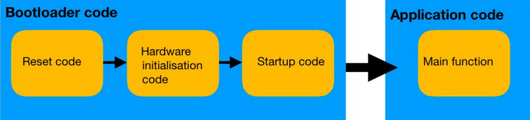
In more complex systems, bootloaders may also handle tasks like firmware updates, security checks, and communication with external peripherals. However, for this tutorial, we’ll focus on the simplest form of a bootloader to get you started.
Setting Up the Development Environment
Before diving into the code, let’s set up the necessary tools:
Tools Required:
- IDE: An integrated development environment from STMicroelectronics, I use vscode but it’s easier to go with STM32IDE.
- GCC Toolchain: not needed if you are using STM32IDE, if you are using vscode you should install the toolchain from here.
- Ceedling: for building the binary .
Hardware Required:
- STM32F4 Discovery Board: This tutorial targets the STM32F4 series, specifically the STM32F407VGT6.
Setup Instructions:
- Install STM32CubeIDE: Download and install it from STMicroelectronics’ official website.
- Install GCC Toolchain: Ensure you have the ARM GCC toolchain installed. This usually comes with STM32CubeIDE.
- Connect the STM32F4 Board: Use a USB cable to connect the board to your development machine, or if you don’t have the board like me you can use renode.
Writing the Bootloader Code
Memory Layout and Vector Table
The STM32F4 has a memory layout that includes various regions for different purposes (e.g., code, data, peripherals). The vector table, which contains the addresses of the exception handlers and the reset vector, is usually located at the start of the flash memory, we will go back to talk about the vector table later.
Let’s start by setting up the reset handler:
|
|
Minimal Hardware Initialization
The bootloader needs to initialize the hardware minimally. This includes setting up the system clock and configuring any necessary GPIOs:
|
|
Loading the Application
The core functionality of a bootloader is to load and execute the main application. For simplicity, we’ll assume the application is already flashed at a specific memory address:
|
|
Testing the Bootloader
Now that we’ve written our simple bootloader, it’s time to test it:
-
Compile the Bootloader:
- Use STM32CubeIDE to compile the bootloader code.
-
Flash the Bootloader:
- Flash the compiled bootloader onto the STM32F4 microcontroller using OpenOCD or the built-in tools in STM32CubeIDE.
-
Load a Simple Application:
- Create a simple application (e.g., a program that blinks an LED) and flash it to the address defined as
APP_ADDRESS.
- Create a simple application (e.g., a program that blinks an LED) and flash it to the address defined as
-
Test:
- Reset the board. If everything is set up correctly, the bootloader will initialize the hardware, load the main application, and the LED will start blinking.
Adding Basic Features
LED Blinking
To make the bootloader visually indicate its operation, you can add a simple LED blink before jumping to the main application:
|
|
Basic Error Handling
You can also add basic error handling to check if a valid application is present before attempting to jump:
|
|
Conclusion
In this blog, we’ve walked through creating the simplest bootloader for the STM32F4 from scratch. We’ve covered the basics of what a bootloader is, how to set up the development environment, and how to write and test a minimal bootloader. We’ve also explored adding basic features like LED blinking and error handling.
There are many ways to expand this bootloader, such as adding UART support for debugging, handling firmware updates, or implementing security features. I encourage you to experiment and build on this foundation to suit your project needs.
References and Further Reading
- STM32F4 Reference Manual
- Cortex-M4 Technical Reference Manual
- STM32CubeIDE Documentation
- ARM GCC Toolchain Documentation
This guide should help you create a simple bootloader from scratch for your STM32F4 platform. Happy coding!
Note to Readers:
This blog post is just the beginning of a series where we’ll build and refine our custom bootloader for the STM32F4. While we’ve covered the basics here, there are still many pieces to explore, such as advanced debugging techniques, handling firmware updates, and adding communication protocols like UART. These topics, along with more complex features, will be detailed in the upcoming parts. Stay tuned for more!